2012

Sedimentation Tank Hydraulics, Spring 2012

Jill Freeman, Mahina Wang, Matthew Hurst, Saied Khan, Yiwen Ng

Abstract:

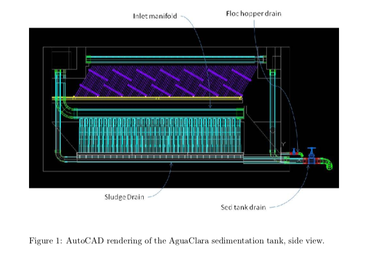
A floc blanket is a dense, fluidized bed of particles that forms in the sedimentation tank. It helps to reduce effluent turbidity by trapping small flocs and reduces clean water waste through less frequent draining of the sedimentation tank. Floc resuspension is necessary for floc blanket formation so that flocs are recirculated through the tank instead of settling on the tank bottom as sludge. Research was conducted to examine the effectiveness of the retrofitted Marcala sedimentation tank. At high influent turbidities, a steady floc blanket was obtained, but performance was slightly compromised when the influent turbidity was lowered to simulate Marcala conditions during the dry season. A floc blanket visibly formed with an influent turbidity of 5 NTU after about 1 week but “seeding” the tank with coagulated flocs will minimize floc blanket formation time. Images were also acquired for hindered sedimentation velocities of 0.6 mm/s, 1.2 mm/s, and 1.6 mm/s and analyzed with a floc-water interface program using a region of interest to better understand hydraulic processes within a floc blanket. Complete settling curves from this data confirmed wall effects significantly affect settling velocity. A floc hopper proved to be effective at controlling the height of the floc blanket when the accumulated flocs were drained at an adequately high flow rate. A lower alum dose of about 39 mg/L for an influent turbidity of 100NTU resulted in a less sticky sludge that could be more easily drained from the hopper.

Sedimentation Tank Hydraulics, Summer 2012

Danielle Feng, Jill Freeman, Cari Gandy

Abstract:

In the sedimentation tank of an AguaClara water treatment plant, water flows through the inlet manifold with vertical diffusers that channel the water into the bottom of the tank as a line source. As water exits the vertical diffusers, a semi circular half pipe jet reverser directs the water upward to resuspend flocs to form a floc blanket, or a dense, fluidized bed of particles, in the sedimentation tank below the plate settlers. A floc blanket increases the particle removal efficiency of the sedimentation tank by capturing smaller flocs that would otherwise escape through lamellar sedimentation. A floc blanket also leads to less clean water waste because without a floc blanket, sludge builds up at the bottom of the tank and will require constant draining. While current plant designs use a 0.5” radius jet reverser and centered jet placement, other jet reverser sizes and jet placements were explored to increase floc resuspension and floc blanket stability. A 1.5” radius reverser with asymmetric jet placement was found to be the optimal design for floc resuspension. Floc blanket stability in relation to coagulent dose was also explored, and optimal alum doses for several influent turbidities were determined.

Sedimentation Tank Hydraulics, Fall 2012

Frances Ciolino, Hongyi Guo, Ethan Yen

Abstract:

The sedimentation tank hydraulics team this semester focused on optimizing the floc hopper. Our main goal was to learn more about the floc hopper geometry and reasons for floc blanket failure. We started the semester by looking at the vertical sedimentation velocity. This velocity is controlled by the flow into the tank and affects how fast the particles settle. If this velocity is too high or too low, the sedimentation tank will not form a proper floc blanket.

We also looked into how the plan view area of the floc hopper would effect the floc blanket formation and performance. Changing the size of the floc hopper effects how much of the area allows for up-flow of the water and how much captures the flocs. In our current experiments we are trying different sizes at different wasting rates. We are looking for a size and rate that keeps the plant running efficiently, meaning the least amount of water wasted while keeping the water leaving the plant clean.

One of the ideas we are working on is continuous wasting of the flocs. The idea behind this is to allow for constant removal of flocs instead of collecting the flocs and then manually opening a valve to let them leave the tank. When the wasting rate is optimal, the flocs will be allowed to compact before they are removed so that the least amount of water is lost in the process. Our last experiment looked at finding the proper wasting rate where the rate of particles flowing into the floc hopper is the same as the rate at which the particles are being removed.

aguaclara+logo.png

Chemical Dose Controller, Spring 2012

Frank Owusu-Adarkwa, Julia Mertz, Ruju Mehta

Abstract:

Continuous, accurate chemical dosing is an essential part of AguaClara plant function. Proper dosing ensures effective flocculation, sedimentation, filtration and disinfection. The chemicals that must be added at different points during the water treatment process are coagulant (PACl or Alum may be used) and chlorine. The linear chemical dose controller (LCDC) is a device that the plant operator can use to directly set doses of coagulant and disinfectant based on the flow rate into the plant. Previous LCDC designs have only been configured to add coagulant prior to flocculation. The triple-doser design is capable of adding coagulant before the influent water enters the stacked rapid sand filter and of adding chlorine for disinfection before the treated water enters the distribution tank. The Spring 2012 team is introducing a more sophisticated LCDC device that will allow the operator to set and monitor the two doses of coagulant and the dose of disinfectant, for a total of three chemical doses, on a single dosing apparatus. In order to ensure accurate chemical dosing, we are testing and documenting the calibration of the new LCDC. Ultimately, we will determine a method for the triple-armed dosing mechanism to be built and added to plants on site, putting a focus on simplicity and elegance of design so that the AguaClara LCDC can be constructed with local resources.

aguaclara logo.png

Chemical Dose Controller, Fall 2012

David Buck, Andrea Castro, Rudra Koul

Abstract:

Accurate chemical dosing is an essential part of an AguaClara plant. Proper dosing is required for effective flocculation, sedimentation, filtration and disinfection. Coagulant (Poly Aluminum Chloride or Alum) and disinfectant (Chlorine) are chemicals used for dosing in an AguaClara plant. The linear chemical dose controller (LCDC) automatically maintains a linear relationship between the influent 􏰂ow to the plant and the chemical dose. The plant operator therefore only adjusts the dose of coagulant based on the turbidity of the influent water. Previous designs for the LCDC functioned at lower flow rates, but design changes were necessary for increased flows and dosing of two chemicals: a coagulant and a disinfectant. The Fall 2012 team created and refined a prototype of the proposed dosing system design. Also, the team concentrated on system aesthetics by: creating a new counter weight, engraving the lever arm scale, adding an engraved AguaClara logo and anodizing the lever arm assembly. Once complete a refined calibration method was devised and documented and the system was tested for linearity of the chemical dosage with respect to the dosing scale and linear flow orifice meter (LFOM) height changes due to varied plant flow. Both tests resulted in a linear fit with an R2 value of 0.9967 for the chemical dose percent data and an R2 value of 0.9955 for the plant 􏰂ow height data. The maximum percent error in the linear relationship between chemical dosing and dosing percentage was 63%. The maximum percent error in the linear relationship between chemical dosing and the LFOM height change was 34%. Errors were below the desired 10% at all data points except the data point corresponding to the lowest chemical dose, which suggests that the LCDC maintains a linear relationship at higher flows and is less accurate at low chemical flows. Error associated with chemical dosages with respect to the percent dosage can be attributed to the scale being offset from the zero (or pivot) point of the lever arm by approximately two centimeters. Error associated with changes in chemical􏰂flow rate with respect to changes in the plant flow rate can be attributed to the weight of the drop tube assembly.

2012 Fall CDC.png

Floc Recycle Venturi, Spring 2012

Ryan Anthony, Elyssa Dixon, Zac Edwards

Abstract:

The purpose of a venturi is to create a low pressure zone in the contraction of a pipe that can be used to pull􏰄fluid from another location into the existing 􏰄ow against the force of gravity. AguaClara can use this technology to implement floc recycle and decrease the necessary size of the flocculator. A pipe will transport heavily flocculated and turbid water from the floc hopper in the sedimentation tank to the horizontal section of the rapid mix pipe that leads into the flocculator. A venturi constructed in this horizontal portion of the rapid mix pipe will pull this turbid water from the floc blanket into the incoming plant flow and thereby increase the incoming turbidity. The flow of the turbid water transported from the floc blanket to the rapid mix pipe is dependent upon difference in head at the end of the system compared to the head in the throat of the venturi. By recycling the turbid water, a greater floc volume fraction will be present at the beginning of the flocculator to increase collisions and thereby reduce the amount of time that the water must spend in the flocculator; this, in return, will reduce the size of the flocculator and reduce material and construction costs.

2012 Spring Venturi.png

EStaRS, Fall 2012

Mihir Gupta, Kris LaPan, Rachel Proske

Abstract:

The use of filtration units for the treatment of drinking water is a common practice in engineering design. However these units are generally used for the treatment of large volumes of water. To improve upon this limitation, a stacked rapid sand filter was designed for low 􏰃ow rates. Work for the semester began with an existing filtration unit which did not contain sand, due to predicted failure from large head losses in filtration and backwash. The existing design was modeled in AutoCAD 2013 to provide an illustration of the system. Updates to this drawing were completed and will continue to be as fabrication phases occur. One of the primary tasks was to develop a mathematical model in MathCAD to calculate the flows and head losses throughout the system. The model was completed for filtration and backwash, and includes calculations for both cycles with and without sand present. Hydraulic testing was completed to determine the head losses in filtration and backwash, risk of sand transport through the backwash pipe, and 􏰃ow rates. These measurements and observations were compared with the mathematical model to determine its validity. According to head loss values obtained from the mathematical model, several changes were made to the filter prototype. Such fabrications included complete reconstruction of the backwash pipe, changing of valve types, and installation of NPT fittings and ball valves. Finally performance testing was completed to determine the effectiveness of the prototype in regards to decreasing effluent turbidity. Overall, it was determined that the filter prototype is highly effective at decreasing turbidity for several influent concentrations at the designed flow rate.

2012 Fall EStaRS.png

Demo Plant, Spring 2012

Sahana Balaji, Muhammed Abdul-Shakoor, Thalia Aoki, Miree Eun, Diana Kelterborn

Abstract:

The AguaClara water treatment process consists of coagulation, flocculation, sedimentation, and filtration, with flow/chemical dose control using gravity. The Demonstration Plant (Demo Plant) is an important educational tool to explain and publicize AguaClara technologies. Currently, a new Demo Plant has been constructed, tested, and documented. This version of the Demo Plant includes a sedimentation tank and a Stacked Rapid Sand Filter (SRSF) as well as a chemical doser and flocculator. The sedimentation tank design is based on the design from the ENGRI 1131 course and includes the formation of a floc blanket. The SRSF shows the new filtration method recently developed by AguaClara. There has also been emphasis on the systematic documentation of both theoretical calculations behind the design and operation of the Demo Plant.

Demo Plant, Summer 2012

Susan Chen, Owen Guldner, Diana Kelterborn

Abstract:

Abstract
The Demonstration Plant (Demo Plant) is an important educational tool to explain and publicize AguaClara technologies. In the Spring of 2012, a new Demo Plant was constructed, tested, and documented which included the two latest AguaClara technologies, a chemical doser and a stacked rapid sand flter (SRSF), as well as the older flocculator and sedimentation tank. However there were still problems with the overall plant layout, the chemical doser, and the SRSF, all of which were dealt with this summer. We completely revised the demo plant structure and system; the SRSF now can completely backwash all four layers, the chemical doser is labeled to include coagulant concentrations, and the overall plant is streamlined for transport and assembly.

2012 Summer Demo Plant.png

Demo Plant – Fall 2012

Owen Guldner and Diana Kelterborn

Abstract:

The Demonstration Plant (Demo Plant) is an important educational tool to explain and publicize AguaClara technologies. In the Spring of 2012, a new Demo Plant was constructed, tested, and documented which included the two latest AguaClara technologies, a chemical doser and a stacked rapid sand flter (SRSF), as well as the older flocculator and sedimentation tank. In the summer of 2012 the demo plant structure and system was completely revised; the SRSF was fixed so that it can completely backwash all four layers, the chemical doser was labeled to include coagulant concentrations, and the overall plant was streamlined for transport and assembly. This semester we finalized construction materials and methods and built four more demo plants to be used at Cornell and abroad.

Ram Pump – Spring 2012

Christine Curtis, Harrison Gill, Teresa Wong

Abstract:

AguaClara plants are driven entirely by gravity. This makes it difficult to provide treated, running water in the plants to fill chemical stock tanks and to provide bathroom service. The Ram Pump sub-team was charged with designing and optimizing a pump to elevate a small amount of water in the plant. The pump works by transferring the momentum from a large amount of water falling a short distance into the potential energy to raise a small amount of water. Initial efforts were focused on designing and building a modular test pump to characterize how ram pumps function and how to optimize performance and ease of construction for specific sites. To accomplish this, we developed a MathCAD document to characterize the testing parameters that we anticipated would most affect the modular pump performance. From these parameters, we were able to collect data regarding cycle time, mass pumped per cycle, and aver- age 􏰃ow of the pump under various configurations. Future teams should explore better data acquisition methods to collect instantaneous velocity data within each cycle. Eventually, decisions regarding the design of the full-scale pump will be made based on experimentation with adjusting these parameters.

2012 Spring Ram Pump.png