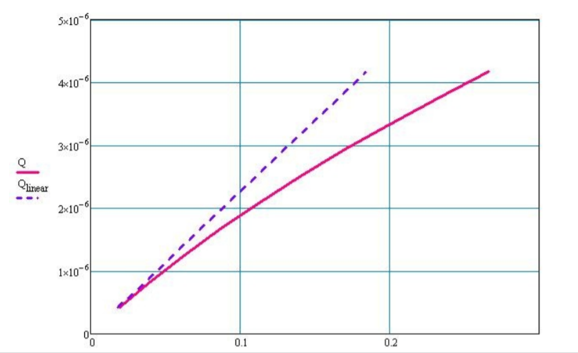
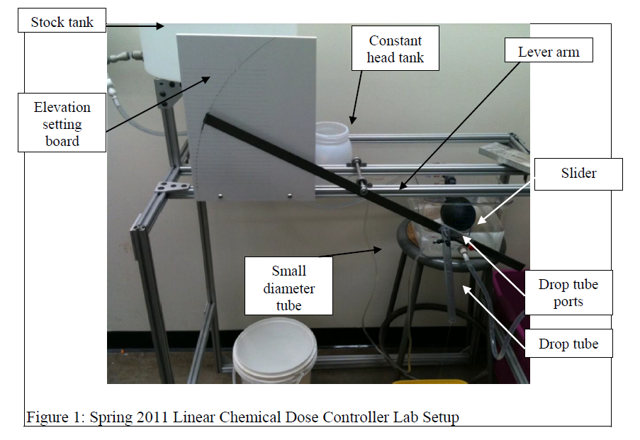
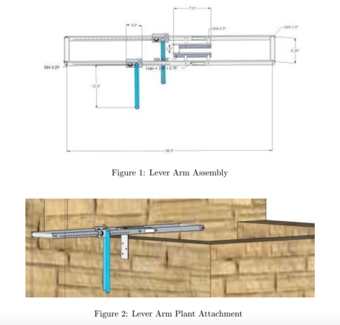
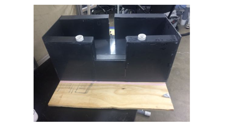
Accurate chemical dosing is an essential part of an AguaClara plant. Proper dosing is required for effective flocculation, sedimentation, filtration and disinfection. Coagulant (Poly Aluminum Chloride or Alum) and disinfectant (Chlorine) are chemicals used for dosing in an AguaClara plant. The linear chemical dose controller (LCDC) automatically maintains a linear relationship between the influent flow to the plant and the chemical dose. The plant operator therefore only adjusts the dose of coagulant based on the turbidity of the influent water. The Spring 2013 team has had two lever-arm assemblies fabricated by Hancock Precision based on the Fall 2012 design with additional improvements, such as having one end rod of the lever arm made up entirely of stainless steel instead of having a stainless steel rod placed over the aluminum rod and substituting anodization of the lever arm with powder coating, as the latter is more resistant to a corrosive environment. One unit has been sent to Honduras and the other is expected to be utilized in India. In addition to this, we have fabricated the manifold system out of PVC, a chemical resistant material. Through application of the orifice equation, we sized the constant head tank float valve orifice. Through application of a statics equation we determined that the oat valve size could be reduced, allowing the use of a standard 5-gallon bucket for the constant head tank. We fabricated a constant head tank, suspended by a chain and attached to a turnbuckle, which can be easily adjusted during calibration. We have set up a fully functional unit of the coagulant dosing component of the dose controller in the lab, calibrated the unit, and tested the system at our maximum flow rate to compare how the system behaves compared to the model prediction and were below ten percent error. We created a detailed 3-D drawing in Google SketchUp of the current design of the linear chemical doser system including all appurtenances, in addition to creating a parts list, to facilitate future fabrications and assembly. This will not only be helpful for future groups to better understand the dose controller but also make it easier for the manufacturers to build it in the future. We also came up with ideas for protecting the entrance tank oats as water enters the plants at some locations in Honduras, to reduce dosing error.