flow

Flow Controller Calibration, Summer 2008

Introduction:

The flow controller design tool on the Flow Controller page is used to calculate the tube length necessary to achieve a desired flow rate with a certain head loss. It has been observed that the actual flow rates that occur when using the lengths of tube provided by the design tool were consistently much slower than they theoretically should have been. This indicated that there was some problem with the assumptions made by the design tool. The error was most likely due to one of two things. It was possible that the actual diameter of the tubing being used was slightly smaller than the diameter published by the manufacturer, or that there were significant minor losses in the flow controller not being taken into account by the assumption of a linear relationship between flow rate and head loss/tube length. It was decided that rather than having to manually calibrate every new flow controller, it would be better to come up with a new method for finding the tube length needed. The new method would need to take into account the smaller diameter of the tubing and/or the minor losses, and would predict a more accurate flow rate without having to do further manual calculations or having to cut the tube after construction of the flow controller

Chemical Dose Controller, Summer 2010

Monica Hill, Aditi Naik, Ritu Raman

Abstract:

The Summer 2010 Chemical Dose Controller (CDC) Team has spent the summer exploring the challenges associated with manufacturing precise orifices. The team has run a series of tests measuring flow rate on orifices created from Legris polyamide, flare cap fittings, refrigerator caps, and carburetor jets to determine their precision and accuracy. The orifices manufactured from polyamide were deemed inadequate, which caused the team to consider in- house and off-the-shelf manufactured orifices created from brass, which showed much lower deviations from the expected flow rate. This report describes the results of the team's experiments on four different types of orifices and endeavors to set future goals for next semester's CDC Team.

Non-Linear Chemical Dose Controller, Fall 2010

Abstract

Accurate alum dosing is vital for plant operation as it has a great impact on the effectiveness of flocculation and sedimentation. The nonlinear chemical dose controller (CDC) is designed to handle turbulent flow chemical dosing used in conjunction with the newly designed Rapid Mix Tube. In contrast, the linear CDC requires that the chemical flow in the dosing tube is laminar.

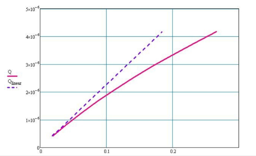
The linear CDC uses the linear relationship between laminar flow and major losses in the doser tube to maintain a constant chemical dose with varying plant flow rates. However, when the flow in the dosing tube is turbulent, the linear relationship no longer exists. In this case, a nonlinear CDC, one that uses minor losses to control flow rates, can be used to maintain a constant chemical dose with the varying plant flow rates. By using an orifice to control chemical flow, the CDC will have the same nonlinear response to increasing flow as the plant flow rate, which is controlled by an orifice. A dual scale system on the lever arm will increase accuracy in dosing at smaller doses.

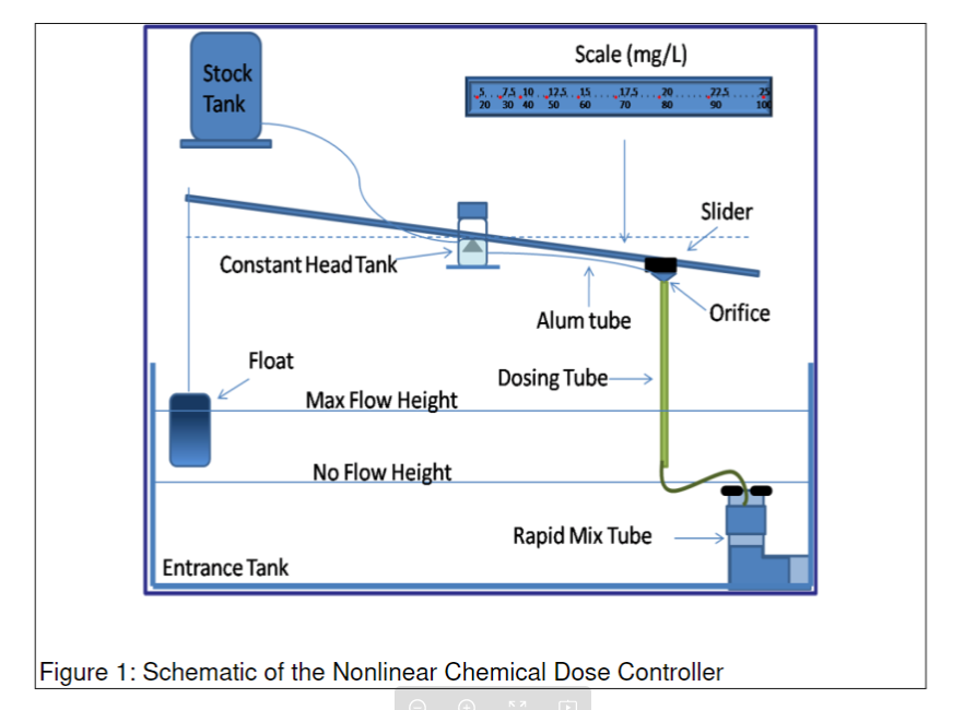
Figure 1 shows a conceptual design of the dosing system. A float in the entrance tank is connected to one end of the lever arm and allows for the arm to move up or down based on varying plant flow rates. As plant flow rates increase, the float rises, and the lever arm connecting the dosing orifice falls increases the elevation difference between the constant head tank and dosing orifice to power chemical flow. As the flow rate decreases the elevation difference decreases and the chemical flow rate slows down.

Figure 1: Nonlinear chemical dose controller schematic

There are two dosing tubes coming out of the constant head tank each with a different size orifice fitting attached to the end. The two different sized orifices allow for the plant operator to dose alum at two different scales, a high and low scale. The operator will choose which orifice will be used based upon the desired alum dose the operator wishes to apply to the water, a parameter that depends on raw water characteristics. The two scales on the lever arm, as seen in Figure 1, correspond to one of the dosing tubes; for instance, the higher scale (20-100 mg/L) will be used when the larger orifice size is needed. The dosing tube which is not in use is merely lifted to a higher elevation than the constant head tank level and is clipped onto a hook to prevent the flow of alum through this unused orifice.

After the alum exits the dosing orifice it flows down through a rigid tube which then injects the alum over a rapid mix conduit which connects the entrance tank and the flocculator. The rapid mix tube has two orifices which create macro and micro eddies to ensure the uniform distribution of coagulant into the raw water.

Low Flow Flocculator, Spring 2012

Ryan Anthony, Elyssa Dixon, Zac Edwards

Abstract

Open ow occulators, like those currently used in AguaClara plants, increase in cost for lower ow rates (less than 5 L s ). AguaClara must be able to meet the need of a wide range of community sizes, so scaling the design for low ow plants is crucial. This report specically analyzes three dierent scenarios that use obstructions within a pipe to remove the geometric constraints that cause the errors found in the current designs. Two scenarios include placing semi-circular baes (similar to those in open ow occulators) within the pipe and maintaining the spacing between and above the baes or maintaining the area between and above the baf- es. The last scenario involves placing balls on a string through the center of a pipe. A table is provided within this report comparing critical values for these occulators for a 3 L/s plant. An initial comparison of the three options shows that the scenario that maintains area above and between baes is the most eective with materials. However, discrepancies with calculations in the approach using balls as obstructions ultimately yields the results inconclusive.