New Process and Structure for Automating AguaClara Plant Designs
The AguaClara Infrastructure Design Engine (AIDE) project team has made great progress this year on AIDE v2 as discussed in two previous blog posts: AIDE Introduction and AIDE Progress Update. The previous blog posts focused on what the AIDE team is working on and their progress towards a minimum viable product (MVP). This post is focused on how the AIDE tool works to efficiently process and structure designs.
In early iterations of AIDE v2, there were distinct separations between the AIDE subteams where one team worked on hydraulic calculations and the other team worked on drawing the plant model. The process of passing information along from one team to another was a difficult challenge to overcome; 3-level design, a new organization to AIDE that uses hydraulic design and build features coupled with design part studios, has made strides in solving this issue. The 3-levels of the design are:
Hydraulic Design Feature (HDF)
Design Part Studio (DPS)
Build Feature (BF)
This solution takes full advantage of Onshape, a cloud-based computer-aided design (CAD) software. Onshape allows users to work in Part or Feature Studios. A Part Studio is useful in developing components and modeling geometry. A Feature Studio contains FeatureScript, a programming language designed by Onshape that allows the design of custom features. For example, the hydraulic calculations which were used to design plant components have traditionally been done in Mathcad or Python, but are now done in FeatureScript within an HDF.
Example functions in the Linear Flow Orifice Meter (LFOM) HDF
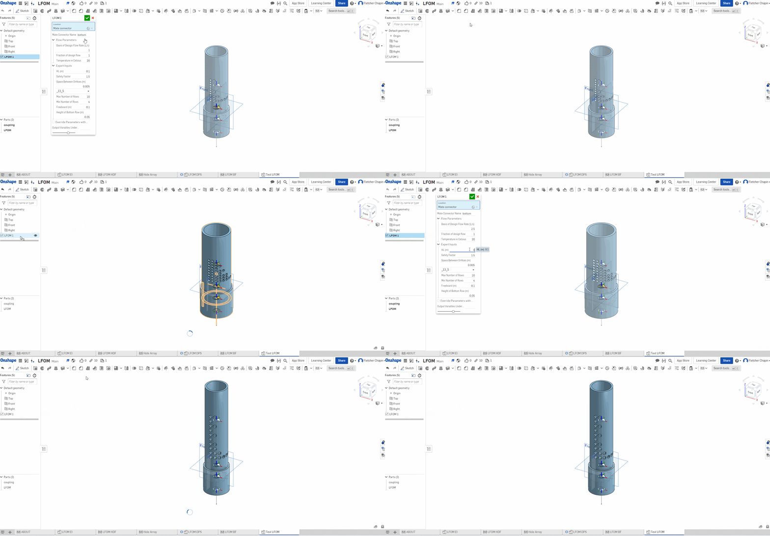
A DPS directly references the variables and outputs from the HDF and combines it with geometric constraints to set the dimensions of the model. Finally, a BF is the entry point for the user. Here, parameters such as flow rate and temperature in addition to expert inputs like head loss are defined.
Demonstration of the LFOM Build Feature
Expert inputs are design constraints and fabrication choices intended to be entered by experienced users. Each has a default value, but anything within an acceptable range can be input. One example of an expert input is the thickness of walls within different components. This variable could be any number without impacting plant performance but relies on the judgement of a structural engineer and is a function of whether the plant is built of concrete or stainless steel. Other examples include treatment process targets such as flocculator collision potential and plate settler capture velocity. The ability to easily change these inputs in a dialog box and then see the resulting plant design will enable AIDE to become a powerful educational tool. Expert inputs are passed between levels of the design using SuperDerive and the overrides string, which is a JSON representation of the expert inputs.
This new integrated design approach has helped to speed up the process of creating unit processes and the team is working hard to meet our goal of a full design for plants in the range of 1-5 L/s by the end of the year.
Blog Post Authors: Fletcher Chapin, Nicole Wang, Tigran Mehrabyan


